

 3D Engine 9 - Light and lighting methods
So ... i'm back again. After a few months i managed to translate some more tutorials.
(I also re-formated czech (what i assume you won't appreciate) + previsous ones and fixed HTML errors so every page should
be displayed ok - according to W3C's HTML 4.01 validator)
Today, we're going to talk about lights and lighting methods. I was thinking about connecting all lighting-concerned tutorials together, but the resulting HTML code would be over 64kB and it's not possible with my Volkov commander (yes, im writing these pages in DOS). No, i'm joking. It will be better to keep tutorials separated, it doesn't have anything to do with filesizes.
That was enough of useless text, so let's get down to coding. Firs, there's list of topics i'd like to discuss:
Color mixing
We have so called RGB system on our computers (many of you may have noticed). Just for sake of clarify: RGB extents for Red Green Blue, which are three components you are able to generate (almost) every color. There will still be colors you can't generate using RGB, but it's not very important for us ...
With RGB there comes also so called color-depth. It expresses how many bits are used for each color component. Most common are 15, 16 and 32 bpp (bits-per-pixel). 15 bits means 5 for each component. With 16 bpp you add one more bit to green (because eye is most sensitive to green. Surprise, huh ? Yes, it's true. Green, not red!) And finaly 32 bpp add alpha channel (used for various transparency and blending effects) so we have four channels R, G, B, A, each 8 bits. Sometimes you can see 24 bpp where is no alpha channel, but there's question of effectivity (32bpp can be read / written asi single int number)
We will slowly move to operations with colors. It'll be nothing special so those experienced can skip this section.
Color multiplication
Most quake-like games uses multiplication. The multiplication operation is simple - you separately multiple each channel with either some value (as grayscale) or another corresponding channel. It used to be (in times of software rendering) MMX - optimalized, since with MMX you can unpack channels to 64-bit register, interspersed with zeros and be multiplied in single instruction. The result looks like this:
Today, we're going to talk about lights and lighting methods. I was thinking about connecting all lighting-concerned tutorials together, but the resulting HTML code would be over 64kB and it's not possible with my Volkov commander (yes, im writing these pages in DOS). No, i'm joking. It will be better to keep tutorials separated, it doesn't have anything to do with filesizes.
That was enough of useless text, so let's get down to coding. Firs, there's list of topics i'd like to discuss:
- Color mixing, basi RGB operations
- A bit of physics
- Lambert's equation
- Three kinds of light
- Summary and optimalisations
- Flat shading (examlpe - game "the life")
- Smooth shading (example - fog)
- Phong shading
- A bit of theorty on Phong
- Using enviroment maps
- Simple enviro-mapping example
- Note about bump-mapping
- Shadow buffer (dynamic shadows)
- One-light example
- How'bout adding more lights?
- HW accelerated shadow-buffer
- Raytracing
- Theory again
- Simple raycasting (just theory)
- Stencil shadows - it wasn't supposed to be here, but ...
- Lightmaps
- Example with Quake ]I[ Arena maps
- Example with raycasting
- Radiosity
- Radiosity theory, global illumination
- Progerssive refinement
- *Very* simple "radiosity" example
Color mixing
We have so called RGB system on our computers (many of you may have noticed). Just for sake of clarify: RGB extents for Red Green Blue, which are three components you are able to generate (almost) every color. There will still be colors you can't generate using RGB, but it's not very important for us ...
With RGB there comes also so called color-depth. It expresses how many bits are used for each color component. Most common are 15, 16 and 32 bpp (bits-per-pixel). 15 bits means 5 for each component. With 16 bpp you add one more bit to green (because eye is most sensitive to green. Surprise, huh ? Yes, it's true. Green, not red!) And finaly 32 bpp add alpha channel (used for various transparency and blending effects) so we have four channels R, G, B, A, each 8 bits. Sometimes you can see 24 bpp where is no alpha channel, but there's question of effectivity (32bpp can be read / written asi single int number)
We will slowly move to operations with colors. It'll be nothing special so those experienced can skip this section.
Color multiplication
Most quake-like games uses multiplication. The multiplication operation is simple - you separately multiple each channel with either some value (as grayscale) or another corresponding channel. It used to be (in times of software rendering) MMX - optimalized, since with MMX you can unpack channels to 64-bit register, interspersed with zeros and be multiplied in single instruction. The result looks like this:
 x
x  =
= 
Here you can download very straightforward example, i'm not going to explain it ...
Color addition
Also "additive transparency". You simply add corresponding channels together. It's a bit more complex, since you have to check for overflow ...
You can use this for wide range of effects. It's heavily used in Quake3:
Also "additive transparency". You simply add corresponding channels together. It's a bit more complex, since you have to check for overflow ...
You can use this for wide range of effects. It's heavily used in Quake3:
 +
+  =
= 
You can also have subtractive blending, which is analogic. It can be used for glass or smoke / etc ...
A bit of physics
You can say what's physics for ? But the most realistic methods are based on exact physics and mathematics. (although we're not going to see any of them in this part) Let's go on ...
Lambert's equation
Mr. Lambert apparently wasn't coder, but he found out a nice thing - the bigger angle between surface normal and vector going from surface to light the less amopunt of light surface receive. You were certainly told something like that in elementar school. My teacher used formulation "the gaps detween places where each ray hit the surface will be greater as the surface tilts"
You need to do this for each pixel of the surface, since amount light won't vary linearily accross the surface, but we won't be always able to do it so we'll be computing light values per pixel or even per poly.
I = Imx * cos(fi)
kde:
I = illumination at certain point
Imx = maximal illumination = light power
fi = angle between normal and point-to light vector (not light-to-point !!)
When you look at the situation, you actually don't have to calculate cosine, but can perform simple dot product :
I hope you can understand this pseudo-code. The surface will have constant illumination unless light move. If you want to have shiny-like surface, where illumination changes also with camera moves, you have to calculate reflection vector, or more simply calculate illumination for light and multiply it with illumination for camera (treat camera position as light position). It's not exactly correct, but it works fine !
Three kinds of light
Maybe you'd say this has nothing to do with physics as well, because there's just one kind of light, but you know, optimalisations are everywhere. This is one of these "loseless" optimalisations - light can be really divided to three different components, first of them is more likely an approximation of error.
In real world, we have shiny (specular) things and matt (diffuse) things. We will utilize behavior of diffuse light - it changes only when lightsource do. But i mentioned three kinds of light - what's third one? Well, it's ambient light - there's tothing like that in real world.
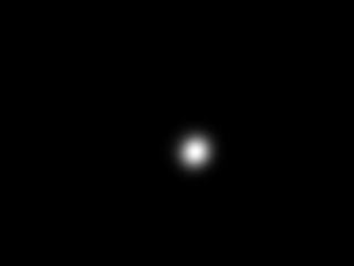
Ambient light
It's simply amount of light every surface will get, no matter direction. In ideal scene it will be zero, in most scenes it close to zero, but not zero at all. You can imagine it like this:
A bit of physics
You can say what's physics for ? But the most realistic methods are based on exact physics and mathematics. (although we're not going to see any of them in this part) Let's go on ...
Lambert's equation
Mr. Lambert apparently wasn't coder, but he found out a nice thing - the bigger angle between surface normal and vector going from surface to light the less amopunt of light surface receive. You were certainly told something like that in elementar school. My teacher used formulation "the gaps detween places where each ray hit the surface will be greater as the surface tilts"
You need to do this for each pixel of the surface, since amount light won't vary linearily accross the surface, but we won't be always able to do it so we'll be computing light values per pixel or even per poly.
I = Imx * cos(fi)
kde:
I = illumination at certain point
Imx = maximal illumination = light power
fi = angle between normal and point-to light vector (not light-to-point !!)
When you look at the situation, you actually don't have to calculate cosine, but can perform simple dot product :
|
I hope you can understand this pseudo-code. The surface will have constant illumination unless light move. If you want to have shiny-like surface, where illumination changes also with camera moves, you have to calculate reflection vector, or more simply calculate illumination for light and multiply it with illumination for camera (treat camera position as light position). It's not exactly correct, but it works fine !
Three kinds of light
Maybe you'd say this has nothing to do with physics as well, because there's just one kind of light, but you know, optimalisations are everywhere. This is one of these "loseless" optimalisations - light can be really divided to three different components, first of them is more likely an approximation of error.
In real world, we have shiny (specular) things and matt (diffuse) things. We will utilize behavior of diffuse light - it changes only when lightsource do. But i mentioned three kinds of light - what's third one? Well, it's ambient light - there's tothing like that in real world.
Ambient light
It's simply amount of light every surface will get, no matter direction. In ideal scene it will be zero, in most scenes it close to zero, but not zero at all. You can imagine it like this:

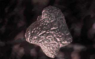
Diffuse light
It's light, perfectly spreaded into all directions, so it doesn't matter where you look from (but there's still Lambert's law!):
It's light, perfectly spreaded into all directions, so it doesn't matter where you look from (but there's still Lambert's law!):
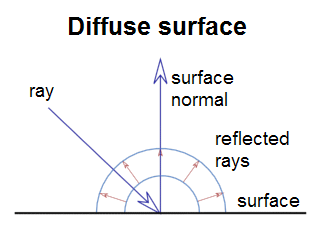
This is emission diagram of of perfect diffuse surface : ray hits surface with certain angle
(this angle matters according to Lambert's law) and then reflects in all directions
equally. Most of older engines used diffuse model:
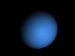
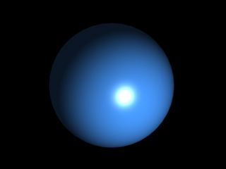
Specular light
It's light, reflected from shiny surface - it's angle of impact (is the word impact correct?) is equal to angle of reflection. So it does matter where camera is:
It's light, reflected from shiny surface - it's angle of impact (is the word impact correct?) is equal to angle of reflection. So it does matter where camera is:
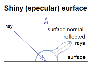
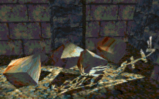
Our specular sphere would look like this :
And the real world ...
There's of course no perfect diffuse or perfect specular surface. It will be some mix of both. So in your material editor you'll say how much will the surface be specular and diffuse. Ambient light should apply on all surfaces equally. So, in the final effect you just sum everything together:
There's of course no perfect diffuse or perfect specular surface. It will be some mix of both. So in your material editor you'll say how much will the surface be specular and diffuse. Ambient light should apply on all surfaces equally. So, in the final effect you just sum everything together:
Summary and optimalisations
As i said, most of older engines used diffuse and ambient only, because they could store them in some way. There were some optimalisations for specular light (like fake Phong), but it was just fake. Most engines also doesn't count only with Lambert's law, but also light attentuation - the truth is the more far surface is, less rays strike it.
Flat shading
We already had flat-shading, but in a very primitive form, without textures and i didn't go to details about what's going on. Flatshading is one of these optimalisations i was speaking about. You simply calculate color of entire triangle and draw it with this color. You can use Lambertian shading or you can use simple rule - when you transform normal vector into cameraspace, the z-component of transformed normal can be used for lighting. Scene will then look like if light was in camera position. If it's exactly 1, face is directed exactly toward camera, ie. shall receive full light (assuming you're not doing attentuation). If transformed normal's z is zero, camera is exactly in face's plane and will receive no light.
In our example we'll do exactly what i described above. We'll multiply transformed z by 256 and convert to integer. Then, during texturing process we'll multiply color of each pixel by this value. We won't attentuate light in this example, but you can easily do that by dividing light's value by Pi * r2. (r is distance of surface from light)
Sometimes you want light to attentuate far from certain distance. Then you use this code:
So - mx_len is distance where light can't reach, len is distance from light to element being lit (polygon center in our case) and min_len is distance where light attentuation begin. Result must be always positive and less or equal to one. I've written this code when writing this tutorial (and didn't check it) so i hope it to be functional. (everyone likes +-1 errors)
As you could read in contents section, example is game "The Life". If yo've learned pascal you certainly know it. It's process, simulating array of living cells. In the beginning you have a few living cells and have some criterions for cell to survive / die / divide. More exactly :
For a living cell :
As i said, most of older engines used diffuse and ambient only, because they could store them in some way. There were some optimalisations for specular light (like fake Phong), but it was just fake. Most engines also doesn't count only with Lambert's law, but also light attentuation - the truth is the more far surface is, less rays strike it.
Flat shading
We already had flat-shading, but in a very primitive form, without textures and i didn't go to details about what's going on. Flatshading is one of these optimalisations i was speaking about. You simply calculate color of entire triangle and draw it with this color. You can use Lambertian shading or you can use simple rule - when you transform normal vector into cameraspace, the z-component of transformed normal can be used for lighting. Scene will then look like if light was in camera position. If it's exactly 1, face is directed exactly toward camera, ie. shall receive full light (assuming you're not doing attentuation). If transformed normal's z is zero, camera is exactly in face's plane and will receive no light.
In our example we'll do exactly what i described above. We'll multiply transformed z by 256 and convert to integer. Then, during texturing process we'll multiply color of each pixel by this value. We won't attentuate light in this example, but you can easily do that by dividing light's value by Pi * r2. (r is distance of surface from light)
Sometimes you want light to attentuate far from certain distance. Then you use this code:
|
So - mx_len is distance where light can't reach, len is distance from light to element being lit (polygon center in our case) and min_len is distance where light attentuation begin. Result must be always positive and less or equal to one. I've written this code when writing this tutorial (and didn't check it) so i hope it to be functional. (everyone likes +-1 errors)
As you could read in contents section, example is game "The Life". If yo've learned pascal you certainly know it. It's process, simulating array of living cells. In the beginning you have a few living cells and have some criterions for cell to survive / die / divide. More exactly :
For a living cell :
- Every cell with one or neighbour less cells dies (loneliness)
- Every cell with more than three neighbours dies (not enough food)
- Every cell with two or three neighbours survuives
- When there are three neighbours arround empty place, new cell originates
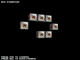
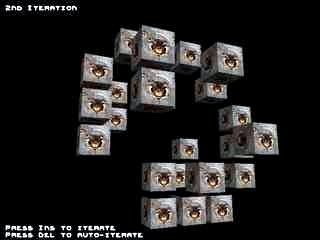
Play arround tweaking it! The roiginal 2D life is worth trying! (see Example.txt) ..
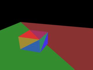
Smooth shading
Smooth shading is one step advanced technique. The color is not determined per-poly, but per vertex and then (smooth) interpolated across surface. You need to know vertex normals. You simply average normals of faces, sharing each particular vertex. It's not very hard to calculate them, but there's one little trap - when the object is textured, you can have more vertices with the same position, but different texture coordinate. There's also a little problem when using faces, instead of polygons, because in that case, simple average isn't ideal solution. Imagine a cube. There can be vertices, sharing three faces or six faces. But there will be vertices, sharing two faces from one side and one face from another sides so the normals won't be 45-degrees, but something close to it. In our case it doesn't matter, but when you'd like to do surface tesselation it will be visible, but now - don't bother.
A weakness of smooth shading is you can't do specular shading fith it, since you can't have highlight in center of polygon, only on it's vertices so as surface rotates (or light moves) the light intensity will seem to vary.
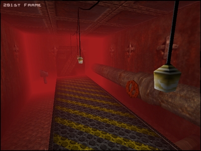
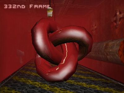
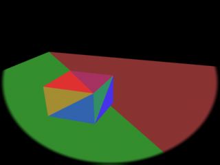
On the other hand, you can use smooth shading for some effects where it doesn't matter so much. For example fog. We will have to subdivide our surfaces, but not so much as we'd have to for specular lighting. You can see smooth shading for example in excellent RPG The elder scrollls : Morrowind. We'll compute lighting and fog in our example. We already know how to compute light, but how about fog ? It's simpler than you could imagine. You have to calculate fog coordinate (0 = no fog, 1 = fully fogged). It's very similar to light attentuation so i won't go to details, you can read code in example. When computing pixel color, you multiply fog color by fog coordinate and add lit texture color multiplied by 1 - fog coordinate. The result will be nice fogged room:
Smooth shading
Smooth shading is one step advanced technique. The color is not determined per-poly, but per vertex and then (smooth) interpolated across surface. You need to know vertex normals. You simply average normals of faces, sharing each particular vertex. It's not very hard to calculate them, but there's one little trap - when the object is textured, you can have more vertices with the same position, but different texture coordinate. There's also a little problem when using faces, instead of polygons, because in that case, simple average isn't ideal solution. Imagine a cube. There can be vertices, sharing three faces or six faces. But there will be vertices, sharing two faces from one side and one face from another sides so the normals won't be 45-degrees, but something close to it. In our case it doesn't matter, but when you'd like to do surface tesselation it will be visible, but now - don't bother.
A weakness of smooth shading is you can't do specular shading fith it, since you can't have highlight in center of polygon, only on it's vertices so as surface rotates (or light moves) the light intensity will seem to vary.
On the other hand, you can use smooth shading for some effects where it doesn't matter so much. For example fog. We will have to subdivide our surfaces, but not so much as we'd have to for specular lighting. You can see smooth shading for example in excellent RPG The elder scrollls : Morrowind. We'll compute lighting and fog in our example. We already know how to compute light, but how about fog ? It's simpler than you could imagine. You have to calculate fog coordinate (0 = no fog, 1 = fully fogged). It's very similar to light attentuation so i won't go to details, you can read code in example. When computing pixel color, you multiply fog color by fog coordinate and add lit texture color multiplied by 1 - fog coordinate. The result will be nice fogged room:
Phong shading
I've already mentioned Phong has something to do with glossy materials and light reflections. Mr. N.H.Phong discovered another rule, similar to Lambert's law, but from a bit different angle of view. The closer is vector of ray of light, reflected from point we are determining brightness for to vector camera is looking the brighter our point will be. Of course, if you told it to some physicist he'd propably had to scream, but it works great for us. It's nice computing but would require square root per pixel, what is unacceptable for us (because of speed)
Simplification, invented by mr. Gouraud is smooth shading we already know (and we already know it's not good for specular lighting), but there is one more method how to do specular lighting ...
Enviroment mapping
Enviroment mapping - based lighting connects gouraud shading with Phong model. Gouraud shading can't have specular highlight in centre of polygon, because we're using only z component of normal so we don't know where our hot-spot (=place of specular highlight) should be. What about trying to use x and y-s of transformed vertex normal. It tells us which direction hot-spot will be. (or more exactly negatice direction) How to use this information ? Simply pre-compute hot-spot to the texture and use transformed normal's x y as texture coordinates. The result will be perfect accurate specular lighting.
Enviroment mapping can be used also for mapping (fake) reflections to objects, it's also heavily used in Quake3 for misc effects.
Here is example on how to compute texture coordinates:
This is piece of DrawObject(), taking care of envmap coordinate computing. Here's an example:
I've already mentioned Phong has something to do with glossy materials and light reflections. Mr. N.H.Phong discovered another rule, similar to Lambert's law, but from a bit different angle of view. The closer is vector of ray of light, reflected from point we are determining brightness for to vector camera is looking the brighter our point will be. Of course, if you told it to some physicist he'd propably had to scream, but it works great for us. It's nice computing but would require square root per pixel, what is unacceptable for us (because of speed)
Simplification, invented by mr. Gouraud is smooth shading we already know (and we already know it's not good for specular lighting), but there is one more method how to do specular lighting ...
Enviroment mapping
Enviroment mapping - based lighting connects gouraud shading with Phong model. Gouraud shading can't have specular highlight in centre of polygon, because we're using only z component of normal so we don't know where our hot-spot (=place of specular highlight) should be. What about trying to use x and y-s of transformed vertex normal. It tells us which direction hot-spot will be. (or more exactly negatice direction) How to use this information ? Simply pre-compute hot-spot to the texture and use transformed normal's x y as texture coordinates. The result will be perfect accurate specular lighting.
Enviroment mapping can be used also for mapping (fake) reflections to objects, it's also heavily used in Quake3 for misc effects.
Here is example on how to compute texture coordinates:
|
This is piece of DrawObject(), taking care of envmap coordinate computing. Here's an example:
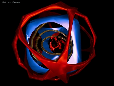
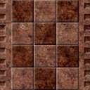
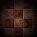
on the top, there are env-maps from Quake ]I[ and in the bottom an screenshot is used as envmap.
(you can see reflecting bridge and lights ...)
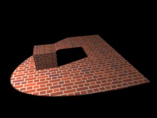
Bump mapping
There is plenty of ways to do bump-mapping. Basicaly it's way to interpret surface of certain material. You can do it with heightmaps (expressing height of each texel of surface) or normal-maps (maps where xyz of surface's normal are stored as rgb values - used on 3D cards)
When using env-mapping, you can do simple bump-mapping by distorting envmap coordinate by derivation of height-map on pixel level. The result will be nice and a bit inacurrate. I won't show you this technique now, wait for OpenGL tutorials.
If you'd like to try it anyway, i tell you you can precompute offset table (table with offsets for shifting envmap coords) when you know it's dimensions. In texture loop you simply add number from offset map to envmap coordinate (you can do it on 16:16 FP level by single add). You can calculate offset with this formula:
bump[x - 1][y] - bump[x + 1][y] is horizontal derivation of bump-map (add to u-coord) and bump[x][y - 1] - bump[x][y + 1] is vertical derivation (multiplied by envmap width so we're adding to v-coord). Result is really amazing:
There is plenty of ways to do bump-mapping. Basicaly it's way to interpret surface of certain material. You can do it with heightmaps (expressing height of each texel of surface) or normal-maps (maps where xyz of surface's normal are stored as rgb values - used on 3D cards)
When using env-mapping, you can do simple bump-mapping by distorting envmap coordinate by derivation of height-map on pixel level. The result will be nice and a bit inacurrate. I won't show you this technique now, wait for OpenGL tutorials.
If you'd like to try it anyway, i tell you you can precompute offset table (table with offsets for shifting envmap coords) when you know it's dimensions. In texture loop you simply add number from offset map to envmap coordinate (you can do it on 16:16 FP level by single add). You can calculate offset with this formula:
|
bump[x - 1][y] - bump[x + 1][y] is horizontal derivation of bump-map (add to u-coord) and bump[x][y - 1] - bump[x][y + 1] is vertical derivation (multiplied by envmap width so we're adding to v-coord). Result is really amazing:


Images from Solstice demo by Sandman
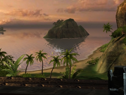
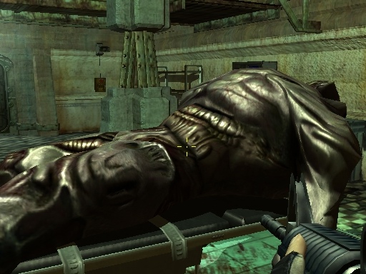
Screenshots from Far Cry game - shows cool ussage of normal-maps
Shadow buffer
As name of this technique prompts - we'll generate some shadows, using some buffer. It's currently being used also on 3D hardware. It's about rendering frame from light-view (we'll have only spotlights for now), but not textured polygons, instead id of polygons. Then remember coordinates for each vertex of polygon in shadowbuffer screenspace. Finally render screen with shadowbuffer, projected as texture onto polygons. Then use straightforward rule - when polygon is visible in light-view, it's lit. Otherwise it's in shadow. So, when rendering polygon, compare polygon id with id from projected shadow-buffer and simply tell it's / it's not in shadow. You will propably render scene with ambient light for objects in shadow and ambient + diffuse + specular for lit objects.
This method of generating shadows was perfectly used in demo The Fulcrum (Matrix, 1997) and I also remember one old game (someone suggested it was called "Seed") using it (that was in time of Tomb-Raider 2)
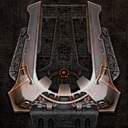
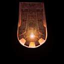
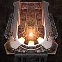
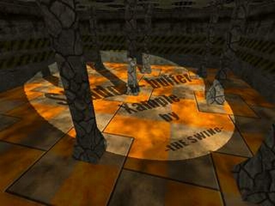
I should also remind you to draw some circle into shadow-buffer (you don't want to have rectangular spotlight, do you ?) Or you can also project some projector map with shadow-buffer, using the smae coordinates. It can be color filter or some image. For example Matrix's older creation - demo Spotilte. You can see perfect grafitti on one of lights:
As name of this technique prompts - we'll generate some shadows, using some buffer. It's currently being used also on 3D hardware. It's about rendering frame from light-view (we'll have only spotlights for now), but not textured polygons, instead id of polygons. Then remember coordinates for each vertex of polygon in shadowbuffer screenspace. Finally render screen with shadowbuffer, projected as texture onto polygons. Then use straightforward rule - when polygon is visible in light-view, it's lit. Otherwise it's in shadow. So, when rendering polygon, compare polygon id with id from projected shadow-buffer and simply tell it's / it's not in shadow. You will propably render scene with ambient light for objects in shadow and ambient + diffuse + specular for lit objects.
This method of generating shadows was perfectly used in demo The Fulcrum (Matrix, 1997) and I also remember one old game (someone suggested it was called "Seed") using it (that was in time of Tomb-Raider 2)
I should also remind you to draw some circle into shadow-buffer (you don't want to have rectangular spotlight, do you ?) Or you can also project some projector map with shadow-buffer, using the smae coordinates. It can be color filter or some image. For example Matrix's older creation - demo Spotilte. You can see perfect grafitti on one of lights:
It was then used in some more demos, but with increasing number of lights you needed
more and more passes to render scene so it was forgotten. Now, in time of powerful 3D-cards
it has been ressurected with slight modification i'm going to describe at the end of this tutorial.
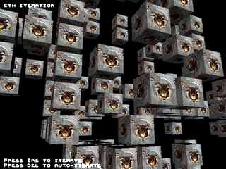
Now something more technical. We'll add three coordinates to each vertex (x, y, z in lightspace. Not perspective correct, just transformed to camera (=light) - space) It should look like this:
It's quite simple (or at least i hope it is) We will first draw our world from light view, drawing id-s of polygons (which have to be unique):
Now something more technical. We'll add three coordinates to each vertex (x, y, z in lightspace. Not perspective correct, just transformed to camera (=light) - space) It should look like this:
|
It's quite simple (or at least i hope it is) We will first draw our world from light view, drawing id-s of polygons (which have to be unique):
Poly-Id buffer
Then draw our circle into it in order to get rid of rectangular spotlight:
Poly-Id buffer with shape of spot
Now, we'll draw polygons (again - slowdown) from camera view and along with texture coordinates
we also interpolate shadow-buffer screenspace coordinates. When drawing, you have to compare
polygon id with id of polygon for each pixel of shadow-buffer. If equall, it means polygon
is visible for light ie. is visible. But there's a catch - we have x y z coordinates
in lightspace, but we need x y in shadow-buffer. First, add to x and y
half of shadow-buffer resolution (early, in FP) then we draw it as we would normally but we're
using lightspace z for perspective correction. Resulting x y (actually i j
in our example code) is shadow-buffer coordinate, but it also can lie out of it's borders so
we'll have to check for it and in case they aren't within shadowbuffer, pixel being drawn is
out of cone angle so it's not lit. It's terribly slow without using 3D hardware so more lights
without some accelereation services (Vesa / DX / OpenGL) are slideshow (we have to draw shadow-buffer
and framebuffer again and again for each light) But the result is worth it:
Result (3D-Max, shadow-buffered)
So we'll examine the rest of example code. It does contain a couple of new functions.
In Raster.cpp there's a new function for drawing polygon id-s to some raster
(ReleaseShBuffer()), working completely same as it's predecessor (ReleaseScreen())
aparts from it doesn't draw textured spans but constant color (polygon id) - filled ones.
Also we have new optimalised function for drawing shadowbuffer polygons (it ignore texture coords)
and drawing objects to shadowbuffer. We're now interested in this one:
This function is used to draw polygons to shadowbuffer (in view of light). We store position of transformed vertex coords at here. At the end we call ShadowPolygon(). It's parameter is id of face, computed along with normals in load_3ds.h. Each face must have unique id !! Next we compute constants for texture / shadowbuffer pos interpolation:
It's just part of it, the rest should be well known. You can see x, y and z in lightspace (= i, j, k here) are perspective correct in cameraspace. (using cameraspace z) The rest of function is effectively the same (there is new code for ijk's) We pass there constants to segments and s-buffer, we'll use them later when drawing framebuffer:
At here, lightspace and cameraspace coordinates are processed separate. It's almost the same (we're doing also perspective correction with lightspace coords: zs = (0x10000 * z_delta) / k; where z_delta is perspective correction shadow-buffer is drawn with - it doesn't have to be equal to screen perspective correction) Now explain Interpolate_Segment():
On the beginning we get texture coords and calculate pixel color (as before). Next we make conversion of i and j (x y in lightspace, now perspective correct) from fixed-point to light so the point to shadow-buffer. Now all we have to do is to compare polygon id and shadow-buffer color.
It's a bit more complicated, because of some rasterization and coordinate transformation errors. We can't compare just single pixel (we could when shadowbuffer contained depth values, but it would require square root per pixel for computing light distance), we'd see face edges. We have to compare 9 pixel box.
In case texel polygon id's doesn't match or pixel isn't inside of light cone we multiply pixel color with ambient light value (we have single light so we can). Here should be also some lighting code for lit pixels or we could do projector filter processing at here. (projector filter can be some image, projected with light or for example video) We have projector map, but it's drawn directly into shadow-buffer, thus it's black & white.
With this technique it's hard to do some shadow-filtering, but we can replace our 9 pixel box with some gauss filter (it's for example 10x10 pixel box, but pixels doesn't have the same weight. It downscales with square distance from center of box - quite expensive) in order to smoothen shadow edges. Now you can download it:
|
This function is used to draw polygons to shadowbuffer (in view of light). We store position of transformed vertex coords at here. At the end we call ShadowPolygon(). It's parameter is id of face, computed along with normals in load_3ds.h. Each face must have unique id !! Next we compute constants for texture / shadowbuffer pos interpolation:
|
It's just part of it, the rest should be well known. You can see x, y and z in lightspace (= i, j, k here) are perspective correct in cameraspace. (using cameraspace z) The rest of function is effectively the same (there is new code for ijk's) We pass there constants to segments and s-buffer, we'll use them later when drawing framebuffer:
|
At here, lightspace and cameraspace coordinates are processed separate. It's almost the same (we're doing also perspective correction with lightspace coords: zs = (0x10000 * z_delta) / k; where z_delta is perspective correction shadow-buffer is drawn with - it doesn't have to be equal to screen perspective correction) Now explain Interpolate_Segment():
|
On the beginning we get texture coords and calculate pixel color (as before). Next we make conversion of i and j (x y in lightspace, now perspective correct) from fixed-point to light so the point to shadow-buffer. Now all we have to do is to compare polygon id and shadow-buffer color.
It's a bit more complicated, because of some rasterization and coordinate transformation errors. We can't compare just single pixel (we could when shadowbuffer contained depth values, but it would require square root per pixel for computing light distance), we'd see face edges. We have to compare 9 pixel box.
In case texel polygon id's doesn't match or pixel isn't inside of light cone we multiply pixel color with ambient light value (we have single light so we can). Here should be also some lighting code for lit pixels or we could do projector filter processing at here. (projector filter can be some image, projected with light or for example video) We have projector map, but it's drawn directly into shadow-buffer, thus it's black & white.
With this technique it's hard to do some shadow-filtering, but we can replace our 9 pixel box with some gauss filter (it's for example 10x10 pixel box, but pixels doesn't have the same weight. It downscales with square distance from center of box - quite expensive) in order to smoothen shadow edges. Now you can download it:
Shadow - Buffer with omni lights
If you don't want to have spot-lights only, but also classical point lights, you'll have to treat each light as more spotlights (most classical sollution is 6, rotated 90° but spotlight angle could be more than 90° so it could be done with less). I hope i don't have to remind you it's not gonna be fast in software :-(.
Shadow - Buffer with more lights
More lights mean more rendering. We have to render ambient-lighted scene first and then render it again and again for each light, but doesn't replace framebuffer pixels with new ones ! You have to add it. In software you could speed things up by drawing single buffer with non-lit polygons so you don't have to interpolate textures any more. It's incredibly slow in software, but Half-Life 2 is built completely on shadow-buffer so you can see it's quite fast with hardware.
Shadow - Buffer with 3D cards
We'll deal tis a bit different with 3D ards. We won't use polygon id's but lightview z-buffer. Next we have to compute distance from light for each pixel of each polygon (it's our square per pixel) Then we compare it (with certain tollerance we of course couldn't afford with polygon id's) with projected depth texture of shadow-buffer. Advantage of this method is one sample will be enough and more - you can filter shadow-buffer, resulting in less blocky shadows.
-tHE SWINe-
Valid HTML 4.01