

 3D Engine 3 - Lights and lighting methods 4 (radiosity)
Radiosity
So, we're gonna chat about radiosity. It sounds kind of mystical, but it's not so much complicated. First a bit of historic data - it started in 1984 on Cornell University on piece of dingy greasy paper with sign Modelling the Interaction of Light Between Diffuse Surfaces on it. Goral has that paper on his conscience, Torrance made it dingy and greasy and Greenberg written what was inside. So, we're dealing with diffuse surfaces - it means radiosity won't help us computing specular surfaces. The idea is simple and in fact it can be used for computing of interaction of any ray-like spreading quantity such as light, maybe heat and with assumption of motionless air and perfetly linear Brown's motion even distribution of deadly smell from decease.
But how did it work ? The world was subdivided to infinite number of small surfaces - patches, while the original geomethry of the world could be thrown away. Every patch has it's own radiative (to be radiated) and illuminative energy (it's illumination) On the beginning, all patches has zero illuminative energy (aparts from objects such as lights) and zero radiative energy (again - but lights). Maybe i didn't mention radiosity is dealing with area lights. Then so-called radiosity matrix was created. It's square matrix with numbers of patches on it's sides, containing form factors. They describe light transmittance from one patch to another. For example when patches aren't visible, form factor will be zero. In case they're directly one against the other one with very small distance between, their form factor should be one. Then you walked trough that matrix, sending radiative energies from every patch to every other patch. Part of energy will go into receiving patch illuminative energy and part to it's radiative energy so it's gonna be reflected ... If you pay attention, you may notice the matrix is too large - because we're reapeating form factors for x -> y by form factor y <- x. Are we ? No, we're not. Form factors for transimittance from patch a to b isn't the same as the one for transmittance from b to a. Sollution was supposed to be done when radiative energy of every patch was zero. After Torrance ate thousand-th tin of sardines, Goral died from fish smell and Greenberg eventually found he's solving two nested infinite loops. (we already know it was too much even for NASA power computers, not mention Torrance's 486 SX DX 2 XXX !) So Torrance grabbed Goral and got him out and in 1988 came Cohen, Chen, Wallace and Greenberg with even more dingy paper, because Chen could't live without his indical kari and old Cohen was fond of eating big chunks of meat. Greenberg was resisting from Wallace to participate in his project, but he claimed his scotch grandfather is paper-maker and their paper comes from free Scottland. Paper, meat - oily, a bit yellow from kari was called A Progressive Refinement Approach to Fast Radiosity Image Generation. This time, things were a bit easier (in fact things are most time easier when you ged rid of double nested infinite loop): We weren't walking trough any matrix (that would eat up some gigabytes of memory anyway), but we pick a patch with greatest radiative energy and "shoot" it. Iterate until radiative energy of patch with greatest radiative energy has radiative energy near-to zero. (as ing. Gandalovich would say : "that piece of crap is going to be iterating yet when you pass your final exam here when you didn't put here terminating condition !" ... and he'd certainly add "yeah, sine tone ... sharp as razor it is !") So this refinement infinitely times cut computing time, because before it was infinite and now it's finite. So we can begin coding
Just a few things before we start. Patches should be small enough so their relative distance is many times greater than their size. (allright, it won't ever work for neighbour patches, but we transmit no energy to neighbour patches, right ?) There are plenty methods for subdividing world into patches. We could take each surface and say - split it 8×8 patches ! That would be a bit waste - and as you can see area of patch is what matters here, we should like to keep all patches uniform size (did it remind you lightmap pixels ? right. we'll show even lightmaps can be used for radiosity) Other method is to subdivide object according to it's size so smaller object results in less patches. Finally there are some hybrid subdivision methods which are dividing surface in progress of sollution as they get into shadow edges or like that ...
A very good thing is, radiosity gives us HDR results (energy of patch can be zero-to-infinite) so we should think about how to display that ... There are a few methods and we'll show two of them. First is simple - just do nothing and see screen is coming white. Allright, we have to carefully adjust initial energies so the result looks fine ... The other method would include some exposition calculation and some nice glow post-effect for parts that are brighter than we can display.
I might add radiosity is global illumination sollution method. It means everything affect everything. You change a piece of geomethry and half of our world's illumnation is going to change. We can also only compute diffuse - diffuse and diffuse - specular interactions. We can't reflect light from specular surfaces, using radiosity, so if we'd like to, we should connect radiosity for example with photon mapping or some raytracing technique. In games, radiosity isn't used very much, since every object, moving in map would cause whole radiosity sollution has to be recomputed. We could trick it with some "local" radiosity, solving illumination only for some part of world in certain distance from viewer, that could work ... But static radiosity is on the other hand quite popular. You can see it in Max Payne, Far Cry or Half Life 2, because these games have cool radiosity lit wolrd, a bit worsened by sharp stencil (shadow-buffer in HL2) shadows ...
Far Cry - soft lightmap shadows for static part of world + stencil for moveable stuff
Computing form factors
Form factors can be figured out from equation :
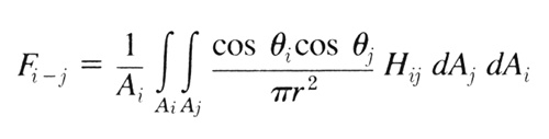
Where i a j are patch indices. Fi-j is form factor
for energy transfer from i to j (not conversely !), r is patch centers distance,
these strange greek characters are radiation angles (angles between patch normal and ray vector)
Ai and Aj are patc areas and dAi and dAj is differential area
(ie. difference of areas) This is (a few mathematical wizards already know) first version of radiosity
(these two integrals mean that double nested infinite loops) Progressive refinement "sounds" like this:
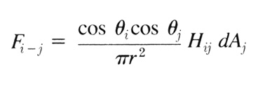
That's similar, but a bit simplified. Mathematically it's completely different
equation so they're not equal. Yes, and i'd forgot about Hij, that is visiblity from one patch to
the other. Usually you cast more rays so you have some fractional visibility, not just 0 / 1. It depends
a bit if you'd like to do realtime radiosity ...
And how does it look ?
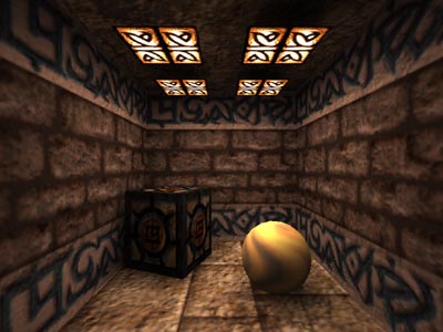
As i told you above - radiosity is for area lights so it results in nice smooth shadows and bright scenes. There's a slight problem with absolutely - reflexive surfaces since they will remain black, but we should know they reflect it's surrounding (use mirror, enviroment map or whatever) Results are this nice:
And how does it look ?
As i told you above - radiosity is for area lights so it results in nice smooth shadows and bright scenes. There's a slight problem with absolutely - reflexive surfaces since they will remain black, but we should know they reflect it's surrounding (use mirror, enviroment map or whatever) Results are this nice:
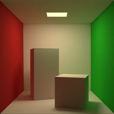
Cornellova box (notice color bleeding !)

Tohle je 3ds max 5 (maybe fake, but could be radiosity)
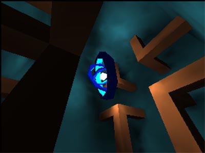
Demo Realtime radiosity 2 (areas, backfacing light aren't completely black)
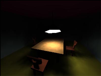
RR2 aswell (illumination on the table right below the light is > 255)
Co my s tím ?
So ... we know mathematical implementation, but there are also hemicubes ! Hemicube is simply half of cube, looks like this:
So ... we know mathematical implementation, but there are also hemicubes ! Hemicube is simply half of cube, looks like this:
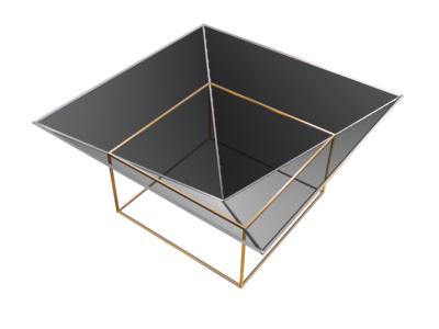
What is it for ? It's simple - you take your rasterizer, put the camera into the centre of patch
(which is also center of cube, this hemicube is part of), set FOV to 90 degrees and render front
wall of hemicube, then also it's sides. (you can see camera's FOV set to render front wall)
We don't draw colors, but our favorite poly-id and when everything is drawn, every patch will
receive energy proportional to number of pixels with it's id in hemicube. How much ? Sum of all
transfered energies must be equal to radiation energy of patch. But how to distribute it ?
Well, hemicube in fact solve part of radiosity equation. There's differential area (more pixels -> more energy),
there's distance (distant patches will occupy less pixels), there's also visibility and finally
there's cos() of receiving patch angle (more dip = less pixels). We should also take distributing
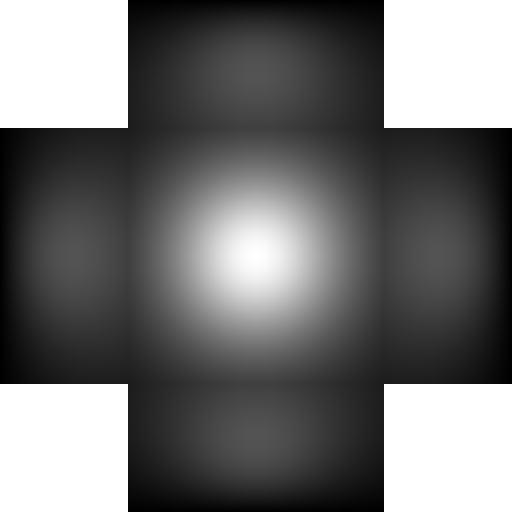
patch angle into account. It's done by map, assigned to all walls of cubemap and containing
weight values of each pixel. What should it exactly contain ? Well, it will be our cosine as
sides of hemicube shouldn't transmit so much of energy as it's front. There's also a little
error in pixel sizes, because we converted hemisphere (that's how we should meassure receiving
patch areas) into hemicube so pixels near center of front wall are in fact bigger than pixels
on the sides:
You can see projection of two pixels from cubemap onto sphere - and as you can see, they do have
different area. So we'll have to write some code for computing hemicube form factors. These will be two
maps, one for front wall and one for sides (all sides are equal)
We should also use ambient light as sum of all radiative energies of all patches,
so we won't see scene brighten gradually, instead we'll see shadows to rise ...
I was talking about color bleeding. How to handle this ? When distributing energy,
some part of energy comes to illumination and some will be radiated. And that radiated energy should change
it's color, according to surface color on the patch ...
When we sum it all together, we have to zero all energies (apart from lights)
and emit radiative energies of patches with gratest readiative energy. (it will be propably lights
and when lights energies are emitted, some patches beneath it will come to act) We should sum all
radiative energies to get ambient color. Assuming radiative energies (and also ambient light)
will drop hyperbolically (ie. it will drop fast in first few seconds and then it will be infinitely
approach zero) so it may take a long time to compute. You can precompute patch colors and then
render it as gouraud-shaded patches as in this VRML demo from Helios:
Helios32 (běží interaktivně ve VRML97)
I might add vertex color is computed as average of patch colors, sharing this vertex.
... what about realtime ?
Of course it's possible to do realtime (we have RR2 demo, right ?) It's done simply - there's not much lightsources, there's not too much patches and using per vertex lighting is also quite cheap. In such a sollution you will set minimal radiation energy quite high so it's done quite fast. On the other hand it's not very accurate. You can also use textures for radiative and illuminative energy, while radiative energy can have smaller resolution than illuminative. (the error won't be much visible if visible at all)
Simple radiosity processor
So. The first one will be real simpleton. We get 3ds file with subdivided surfaces, object names will be "__light" or some other for non-light patches (we can substitute face = patch) We will also say the patches have approximately same area so the differential areas are always one so can be left out. We won't do hemicube at here, but we'll try simple raytracing. Hemicube will come in next example. I decided to add textures (and then fell to black-and white lights becuse of performance ...) So, we have our first function, performing n radiosity iterations :
It's quite simple. We pick face with greatest radiative energy, distribute that energy, set his raduiative energy to zero. Then recompute vertex colors so we can see process of energy distribution. I should go trough f_FormFactor():
This is very simple interpretation of the second (progressive) refined radiosity equation. Get center of the second patch, compute ray, visibility, add distance factor and ray / normal angles. The result is quite non-precise form factor, but for now it's enough. Function f_Visibility() return patch vivibility value. That should be value in range <0, 1> (that's why it return float), but we do just single check so the result is value {0, 1}. I should mention the raytracing function is clearly bottleneck, some BSP would do a great deal.
... and how to put it together ? Simply load world, initialize patch (face) energies, do some iterations of radiosity and simply draw frame. But how ? We have our HDR values ! This time i'll assume values in 0 - 65535 range so we should fit into 16:16 fixed point value for interpolation illumination accross the surface. We just have to change color modulation a bit:
Where n_color is diffuse color of surface and i1 is 16:16 FP illumination. Everytime we move it 16 bits right what we shouldn't, because we're loosing accuracy. We also need to check for color overflows. The last thing we should do is to hope our optimizer will handle repeating expressions and make code run fast.
So that much for the first example. It wasn't so complicated at all. You'll notice the result is quite slow, but i won't bother optimalizing this - it's just your first date with mrs radiosity. You can sit with her, watching as she converges to the sollution. The very definition of romantic moments :o). You can switch on/off HDR, but it won't be any faster since switch off mean "clamp all illumination values up to 255" ... it's just about seeing the difference.
... what about realtime ?
Of course it's possible to do realtime (we have RR2 demo, right ?) It's done simply - there's not much lightsources, there's not too much patches and using per vertex lighting is also quite cheap. In such a sollution you will set minimal radiation energy quite high so it's done quite fast. On the other hand it's not very accurate. You can also use textures for radiative and illuminative energy, while radiative energy can have smaller resolution than illuminative. (the error won't be much visible if visible at all)
Simple radiosity processor
So. The first one will be real simpleton. We get 3ds file with subdivided surfaces, object names will be "__light" or some other for non-light patches (we can substitute face = patch) We will also say the patches have approximately same area so the differential areas are always one so can be left out. We won't do hemicube at here, but we'll try simple raytracing. Hemicube will come in next example. I decided to add textures (and then fell to black-and white lights becuse of performance ...) So, we have our first function, performing n radiosity iterations :
|
It's quite simple. We pick face with greatest radiative energy, distribute that energy, set his raduiative energy to zero. Then recompute vertex colors so we can see process of energy distribution. I should go trough f_FormFactor():
|
This is very simple interpretation of the second (progressive) refined radiosity equation. Get center of the second patch, compute ray, visibility, add distance factor and ray / normal angles. The result is quite non-precise form factor, but for now it's enough. Function f_Visibility() return patch vivibility value. That should be value in range <0, 1> (that's why it return float), but we do just single check so the result is value {0, 1}. I should mention the raytracing function is clearly bottleneck, some BSP would do a great deal.
... and how to put it together ? Simply load world, initialize patch (face) energies, do some iterations of radiosity and simply draw frame. But how ? We have our HDR values ! This time i'll assume values in 0 - 65535 range so we should fit into 16:16 fixed point value for interpolation illumination accross the surface. We just have to change color modulation a bit:
|
Where n_color is diffuse color of surface and i1 is 16:16 FP illumination. Everytime we move it 16 bits right what we shouldn't, because we're loosing accuracy. We also need to check for color overflows. The last thing we should do is to hope our optimizer will handle repeating expressions and make code run fast.
So that much for the first example. It wasn't so complicated at all. You'll notice the result is quite slow, but i won't bother optimalizing this - it's just your first date with mrs radiosity. You can sit with her, watching as she converges to the sollution. The very definition of romantic moments :o). You can switch on/off HDR, but it won't be any faster since switch off mean "clamp all illumination values up to 255" ... it's just about seeing the difference.
last one's without HDR
... these textures initially showed up as bad ones, because they're too dark.
You can toggle them by pressing "T" key. You can also toggle radiosity iterating by "L" or HDR with "H".
Have fun with this one !
... And that's all ?
Ne, to zdaleka není všechno. Ono ... k tomu HDR - ono se obraz vyrenderuje do float bufferu (pro r, g a b složku je float hodnota), nebo do dvou bufferů, z nichž jeden tvoří spodních 8 bitů a druhý vrchních 8 bitů barevných složek. Buffery se potom zprůměrují a tím se spočítá průměrná světlost. Podle ní se potom upraví kontrast a jas a výsledný obraz se ořízne do normálního 32bpp bufferu.
Občas se ještě dělá to, že se vezme kopie obrazu, kde zůstanou jen hodnoty RGB přesahují určitou mez. Tenhle buffer se potom prožene nějakým blurem a přičte se k obrazu. Vznikne potom krásný efekt, kdy světlé věci září i do okolí ... Asi si to potom zkusíme s OpenGL ...
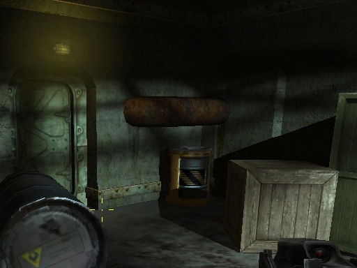
HDR používá po zpatchování třeba taky Far Cry (obrázek), a když už jsem u Far Cry, měl bych připomenout že při počítání průměrné světlosti by se potom měly zachovat také nějaké meze, jinak dopadnete jako FarCry, kde malá žárovička v tmavé místnosti vypadá jako sluníčko :o)
... And that's all ?
Ne, to zdaleka není všechno. Ono ... k tomu HDR - ono se obraz vyrenderuje do float bufferu (pro r, g a b složku je float hodnota), nebo do dvou bufferů, z nichž jeden tvoří spodních 8 bitů a druhý vrchních 8 bitů barevných složek. Buffery se potom zprůměrují a tím se spočítá průměrná světlost. Podle ní se potom upraví kontrast a jas a výsledný obraz se ořízne do normálního 32bpp bufferu.
Občas se ještě dělá to, že se vezme kopie obrazu, kde zůstanou jen hodnoty RGB přesahují určitou mez. Tenhle buffer se potom prožene nějakým blurem a přičte se k obrazu. Vznikne potom krásný efekt, kdy světlé věci září i do okolí ... Asi si to potom zkusíme s OpenGL ...
HDR používá po zpatchování třeba taky Far Cry (obrázek), a když už jsem u Far Cry, měl bych připomenout že při počítání průměrné světlosti by se potom měly zachovat také nějaké meze, jinak dopadnete jako FarCry, kde malá žárovička v tmavé místnosti vypadá jako sluníčko :o)
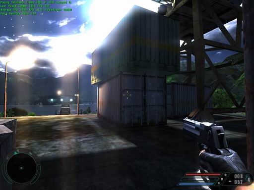
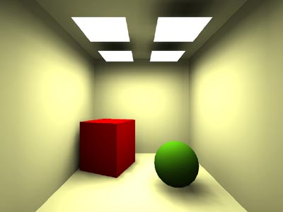
with HDR
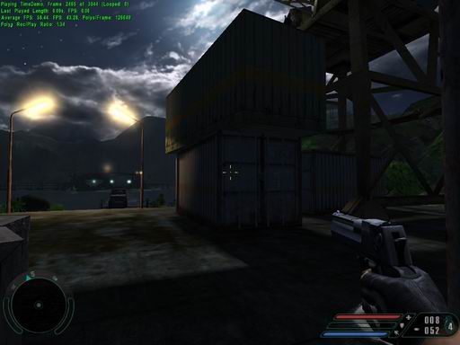
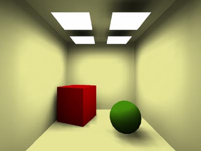
without HDR
The end ..? You gess !
Well, i'm not going to stop torturing you now. There's one more example with lightmaps, using hemicube and doing HDR-like post production. (in the end i didn't write exposure control - i'm too lazy), But the result is worth it anyway. First have a look at how to calculate such a hemicube:
|
Now a bit explaining ... First we have some global variables. First constant is hemicube resolution. Then there are some arrays. p_s_hemicube_buffer and p_s_hemicube_buffer_side are buffers, we're going to render what hemicube "see". (_side is four times, because we're going to display hemicube contents onto screen so we want to remember it whole. THen we have p_hemicube_formfactor and p_hemicube_formfactor_side - form-factors of hemicube pixels. (this time single _side is enough since remaining three would contain the same data) We should now take a look at Calc_HemicubeFormFactors():
On the beginning we calculate f_half_pixel_width - half of hemicube pixel size (width) Hemicube is 1 unit deep and 2 units wide. (like four unit cubes, aligned arround normal vector) Then calculate f_pixel_area - pixel area. In loop we calculate distance from center for each pixel. Then convert it to worldspace distance and calculate form factor:
f_pixel_area / (Pi * (dx2 + dy2 + 1)2)
We do the same for hemicube side, we only have to calculate it's distance from center. The result is nice hemicube we can convert to bitmap using p_Hemicube_Test() function. My result look like this:
Now when we have hemicube, we should find out how to render it. We know patch center (lightmap texel center) and it's normal. It's enough to set up camera, looking away from patch along it's normal and also four "side" cameras as well. Let's see:
|
So. Function gets v_pos (position of patch center), v_normal (it's normal), p_svet (world geomethry) and v_radiative (radiative color; it's classic RGB, but stored as floats and not clamped to <0, 1>) On the beginning we set up camera as we already did it. We pay attention so our "up" vector is never colinear with direction vector. Then call Set_FormFactors() to set corresponding table with form-factors and radiative color. Then make two more calls, namely SubWindow() that set sub-window resolution, must be always less than image resolution and Clipper() that set valid sub-window area (it's difference, because SubWindow(), change resolution and perspective correction constant so camera direction intersect image in center, but when calling Clipper(), it simply clip image. It's useful when drawing sides of hemicube, we need camera direction to intersect bottom edge of image) Then draw world as we always did and call clone of Release_Screen() It draw front side of hemicube. Then rotate camera 90 degrees arround x axis, so view direction lies in patch plane. Set image clipping to half height so we get only part of image that is above patch plane (that's exactly what we need) and draw it again. Then rotate camera again 90 degrees, this time arround y axis, making camera to look at another side of cubemap. We shouldn't forget to set another form-factor table for sides. How to check if it works ? We could simply copy rectangles on screen:
We can also do it a bit complicated - project hemicube onto hemisphere.
It's fairly simple transformation. Imagine hemicube with it's surface covered with points. Each
point hold value of vector point position - sphere center (sphere, not hemisphere). Now imagine
someone fat stepped onto that hemisphere and ironed it. Now we have our hemisphere on the pavement
(plane) so our points are on it's surface, but they still hold original vector values. That's what
we're going to try to achieve. We can place flat hemisphere somewhere to that raster and for each pixel
compute distance to hemisphere center position in raster and divide them by hemisphere radius in pixels.
This yields x and y vector coordinates. We divided it by radius so it should be unit vector.
It mean when x, y are greater - z is going to be small, vector points near edge of
hemisphere. When x and y are zero, we're in center of hemisphere and z will be 1.
We see we can use this equation:
x2 + y2 + z2 = 1
(there's no square root, because we all know sqrt(1) = 1) From it we can derive z is:
z2 = 1 - x2 - y2
z = sqrt(1 - x2 - y2)
Now we can take this vector, find out it's greatest component (and it's sign) so we know hemicube side it points to. Then we just have to transform that vector to raster coordinates and draw that pixel. We already know that transformation, it's simply perspective correction, while perspective correction constant is 1. We shouldn't forget to multiply it by raster size and add half raster size to translate point [0, 0] to center. My code is here:
If you delete comment mark ahead of Modulate_HemicubeBuffers();, you'll see hemicube image modulated by form-factors. I've left it this way because of speed purposes. The result is nicely looking fish-eye like transform: (it's viewed from another patch than before)
x2 + y2 + z2 = 1
(there's no square root, because we all know sqrt(1) = 1) From it we can derive z is:
z2 = 1 - x2 - y2
z = sqrt(1 - x2 - y2)
Now we can take this vector, find out it's greatest component (and it's sign) so we know hemicube side it points to. Then we just have to transform that vector to raster coordinates and draw that pixel. We already know that transformation, it's simply perspective correction, while perspective correction constant is 1. We shouldn't forget to multiply it by raster size and add half raster size to translate point [0, 0] to center. My code is here:
|
If you delete comment mark ahead of Modulate_HemicubeBuffers();, you'll see hemicube image modulated by form-factors. I've left it this way because of speed purposes. The result is nicely looking fish-eye like transform: (it's viewed from another patch than before)
Now you're propably interested in function for energy "shooting". Classic
model is to draw patch-id buffer and then go trough it's pixels and add corresponding energies
to each patch, certain pixel points to. But we have lightmaps and it would be a bit difficult to
index lightmap texels, although not impossible. Say we have maximal resolution of lightmap 512×512
so index to lightmap take up 2 × 9 = 18 bits (2 times for x and y texel coordinate; 512 = 29)
We have 14 (32 - 18) bits left for lightmap page index, allowing us to have 16k of lightmaps.
(16k = 16.1024 = 16384)
We're going to take some advantage of s-buffer, namely zero overdraw. We'll modify lightmap format so we have 6 float values for each texel (2 RGB triplets for illuminative and radiative energy) We'll illuminate lightmap texels same time we render image for cubemap, because we need lightmap (illuminative) values there anyway - and radiative are just next three floats in row ! We need do some modifications in order to support that format. We need (among others) modify lightmap allocation function. That's simple one:
That's the same function as last time in lightmap-mapping utility. The only change is it alloc 6 floats instead of single __int32 per pixel. Next change is in lightmap content creation function:
It's almost nothing new at here, we just check if certain texel lie on some of faces and if that face has positive radiative energy, we assign it to that texel. We should count on texel area at here ! We assign some energy to illuminative color aswell so lights are bright, instead of black.
I should show you how to render span with such a lightmap format. It's slightly modified function from the previous tutorial example:
We determine diffuse color, texel index in lightmap, multiply it by six (we have six floats per pixel as i explained you above; multiplying by six can be performed a bit faster by adding bit shift left by 2 and 1) Then add 0, 1, 2 to index and we have illumination color values. Then modulate texture color and write to video-buffer. Texture is bilinear filtered, lightmaps are dithered.
I'll show you one more function, used for "shooting" energy along with drawing hemicube contents:
Here we get diffuse color again, calculate index of texel in lightmap, read corresponding form-factor (... see how usefull x and y used for dithering is !) and add corresponding radiative and illuminative energy. When computing radiative energy, we perform some color mixing (radiative and pixel diffuse color) in order to get color bleeding. Then return lit pixel color as we'd normally do so we can render hemicube contents to screen when user like to. Now you should understand how does the example work. I'll put here a brief list of steps it goes trough:
On the beginning we simply find texel with greatest radiative energy in one of lightmap pages, then sequentially go trough all mapping groups and check if texel belongs to one of them. Then we have normal (all faces in group does lie in same plane, remember ?) Then find face containing this texel, return it's id, calculate worldspace position, return radiative color and clear it in lightmap. Anyway, our rasterizer has some errors and sometimes it happens texel that doesn't belong to none of faces render to hemicube - and get some radiative energy. In that case, we simply clear it and try again (that's why all the code is in the loop) When all radiative energies are zero, function return -1.
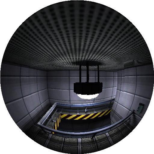
Example code immediately begins shooting energy. You can toggle it by pressing 'I', the 'P' key display radiating patch and one of faces in it's plane, 'F' disable hemicube display, 'G' enables the simple one and 'H' enables spherical one. Pressing 'R' you can toggle radiative energies display instead of illuminative and pressing 'Q' you enable post-production. Lightmaps eventually seems a bit handicapped because texels on borders of objects are for example half-visible and they are darker than they should be. You can solve this by pressing 'B' what causes all lightmaps to blur. You should do it only once when you want screenshot your results, otherwise all shadows will blur away.
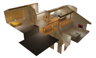
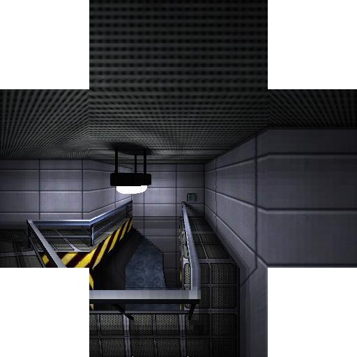
What about results ? I've drawn a room in System Shock - mood and after some half hour (we have high resolution lightmaps - thus lots of patches) it lits perfectly. I've noticed a few errors in lightmap mapping, but i'm not going to solve them now. View some screenshots:
We're going to take some advantage of s-buffer, namely zero overdraw. We'll modify lightmap format so we have 6 float values for each texel (2 RGB triplets for illuminative and radiative energy) We'll illuminate lightmap texels same time we render image for cubemap, because we need lightmap (illuminative) values there anyway - and radiative are just next three floats in row ! We need do some modifications in order to support that format. We need (among others) modify lightmap allocation function. That's simple one:
|
That's the same function as last time in lightmap-mapping utility. The only change is it alloc 6 floats instead of single __int32 per pixel. Next change is in lightmap content creation function:
|
It's almost nothing new at here, we just check if certain texel lie on some of faces and if that face has positive radiative energy, we assign it to that texel. We should count on texel area at here ! We assign some energy to illuminative color aswell so lights are bright, instead of black.
I should show you how to render span with such a lightmap format. It's slightly modified function from the previous tutorial example:
|
We determine diffuse color, texel index in lightmap, multiply it by six (we have six floats per pixel as i explained you above; multiplying by six can be performed a bit faster by adding bit shift left by 2 and 1) Then add 0, 1, 2 to index and we have illumination color values. Then modulate texture color and write to video-buffer. Texture is bilinear filtered, lightmaps are dithered.
I'll show you one more function, used for "shooting" energy along with drawing hemicube contents:
|
Here we get diffuse color again, calculate index of texel in lightmap, read corresponding form-factor (... see how usefull x and y used for dithering is !) and add corresponding radiative and illuminative energy. When computing radiative energy, we perform some color mixing (radiative and pixel diffuse color) in order to get color bleeding. Then return lit pixel color as we'd normally do so we can render hemicube contents to screen when user like to. Now you should understand how does the example work. I'll put here a brief list of steps it goes trough:
- create window, init direct-x, etc ...
- call Calc_HemicubeFormFactors(); - calculate hemicube form-faktors
- load our world and place lightmaps on it Create_Lightmaps("sshock_room_1obj.3ds", &t_svet)
(That's where some faces get radiative energies. it's color is color of nearest light. We should count with texel area !) - load textures
- drawing loop
- find texel with greatest radiative energy (+ his worldspace normal and position)
- render hemicube (along with shooting radiative energy)
- refresh one-pixel frames arround lightmaps
- render screen
- render screen with lower brightness, blur it and add to previous one
- display the result
|
On the beginning we simply find texel with greatest radiative energy in one of lightmap pages, then sequentially go trough all mapping groups and check if texel belongs to one of them. Then we have normal (all faces in group does lie in same plane, remember ?) Then find face containing this texel, return it's id, calculate worldspace position, return radiative color and clear it in lightmap. Anyway, our rasterizer has some errors and sometimes it happens texel that doesn't belong to none of faces render to hemicube - and get some radiative energy. In that case, we simply clear it and try again (that's why all the code is in the loop) When all radiative energies are zero, function return -1.
Example code immediately begins shooting energy. You can toggle it by pressing 'I', the 'P' key display radiating patch and one of faces in it's plane, 'F' disable hemicube display, 'G' enables the simple one and 'H' enables spherical one. Pressing 'R' you can toggle radiative energies display instead of illuminative and pressing 'Q' you enable post-production. Lightmaps eventually seems a bit handicapped because texels on borders of objects are for example half-visible and they are darker than they should be. You can solve this by pressing 'B' what causes all lightmaps to blur. You should do it only once when you want screenshot your results, otherwise all shadows will blur away.
What about results ? I've drawn a room in System Shock - mood and after some half hour (we have high resolution lightmaps - thus lots of patches) it lits perfectly. I've noticed a few errors in lightmap mapping, but i'm not going to solve them now. View some screenshots:
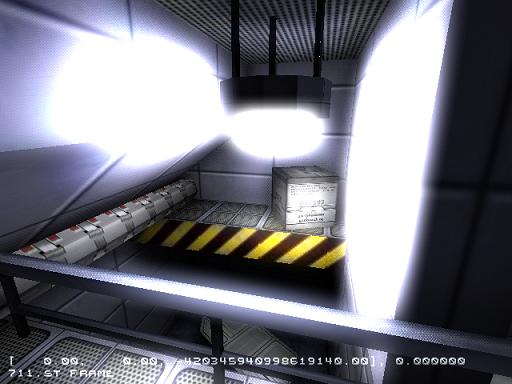
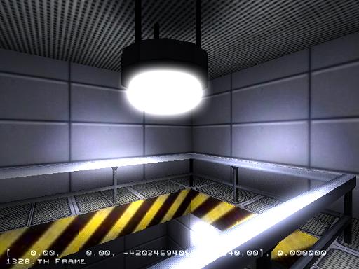
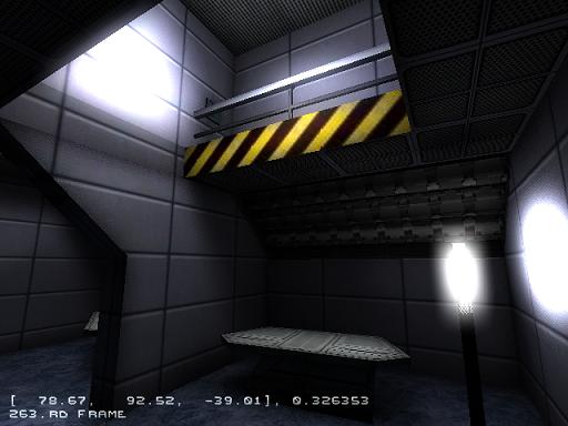
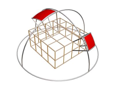
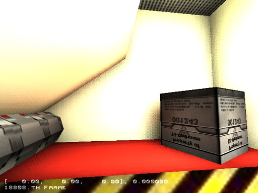
... and eventually one more shot, showing color bleeding in action: (i've switched two textures for
white and red one - result is reddish glimmer you can see on white texture as well as on the box)
So, you can download our tiny
radiosity example 2
... and play arround with it ! We'll do some finishing touches next time and then: first OpenGL tutorial !
-tHE SWINe-
... and play arround with it ! We'll do some finishing touches next time and then: first OpenGL tutorial !
-tHE SWINe-
Valid HTML 4.01